
Custom PEEK Jaw Angle Implants: Virtual Surgical Plan
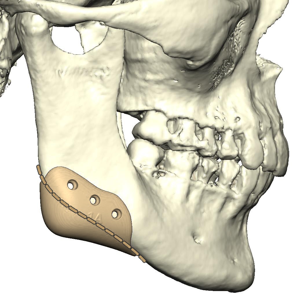
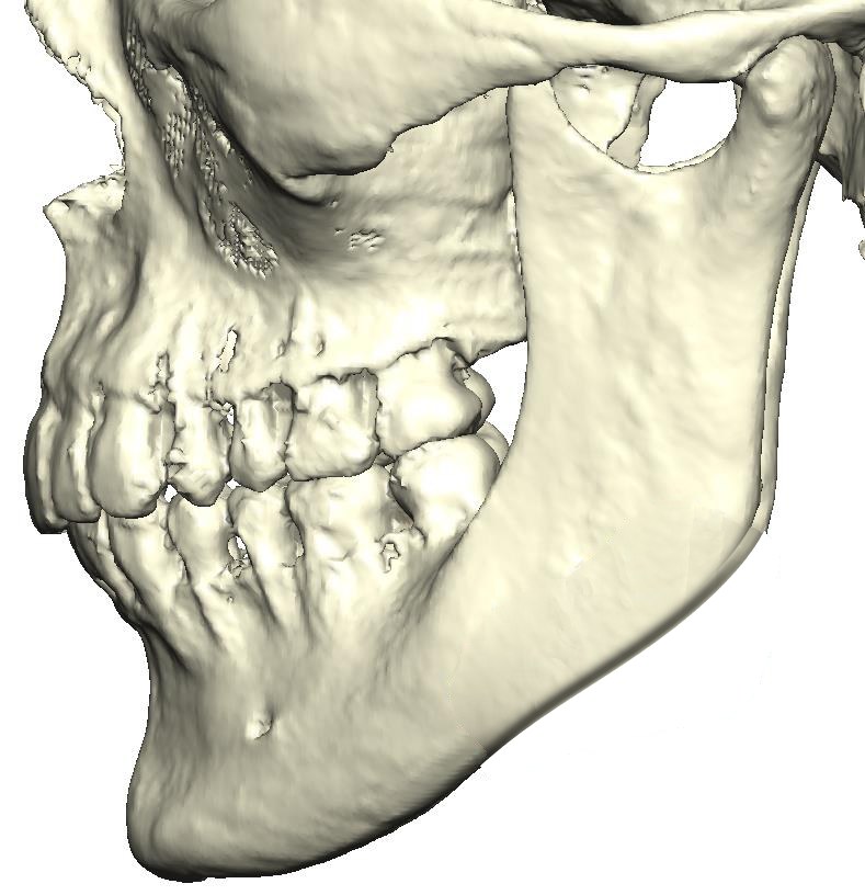
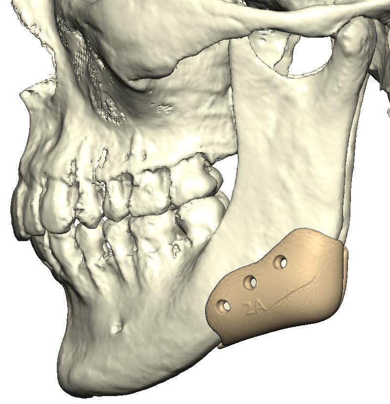
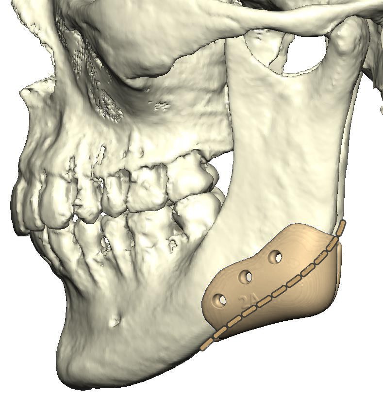
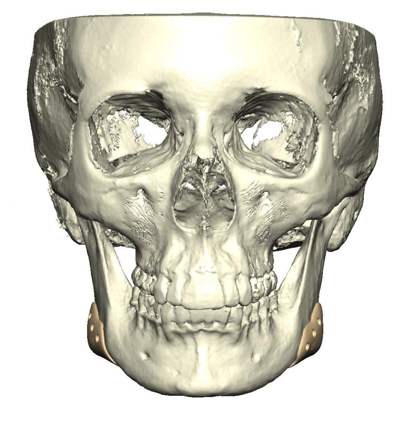
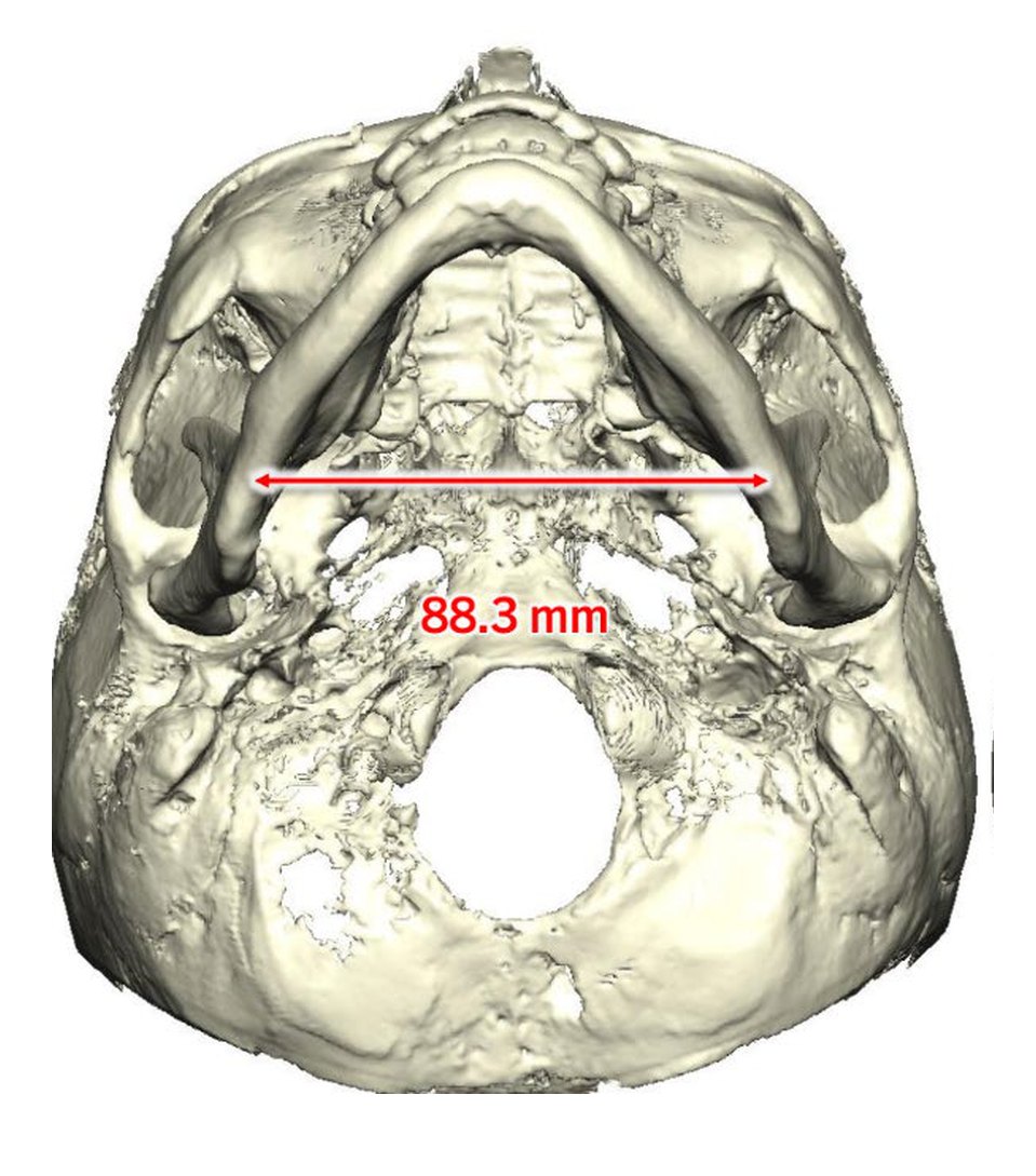
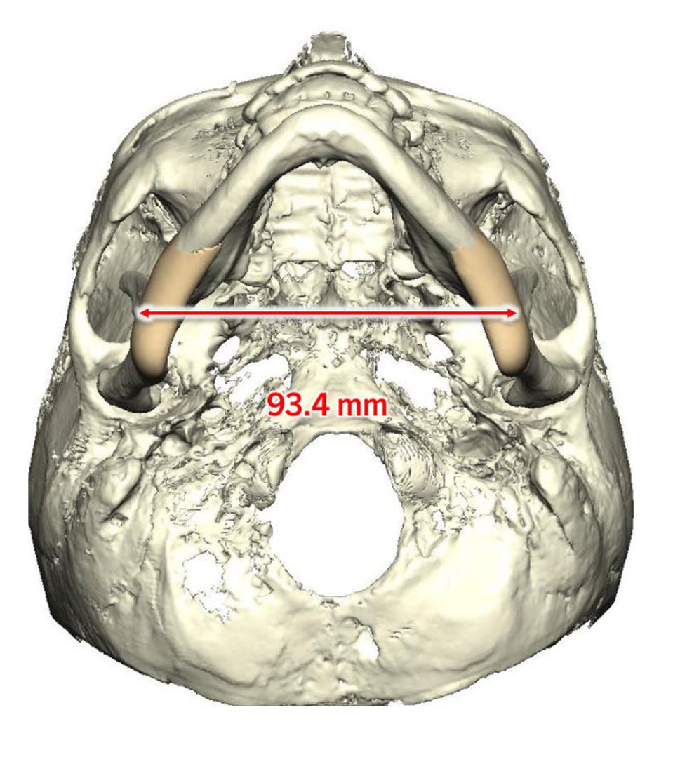
The goal was added vertical length and definition at the jaw angles, for a short ramus and a steep mandibular plane angle. Two patient-specific PEEK implants, one for each side, were designed on a 3D model of the skull from the CT scan to lengthen and define the angles. In the plan, the width between the jaw angles goes from 88.3 to 93.4 mm.
- Type
- Virtual surgical plan
- Goal
- Added vertical length and definition at the jaw angles
- Implants
- Custom PEEK mandibular angle implants, right and left
- Angle width
- 88.3 → 93.4 mm (planned)
- Planning
- 3D CT model, virtual design
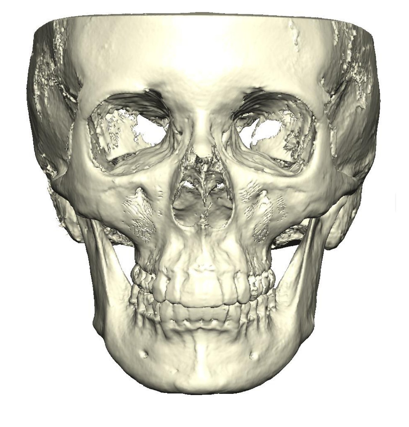
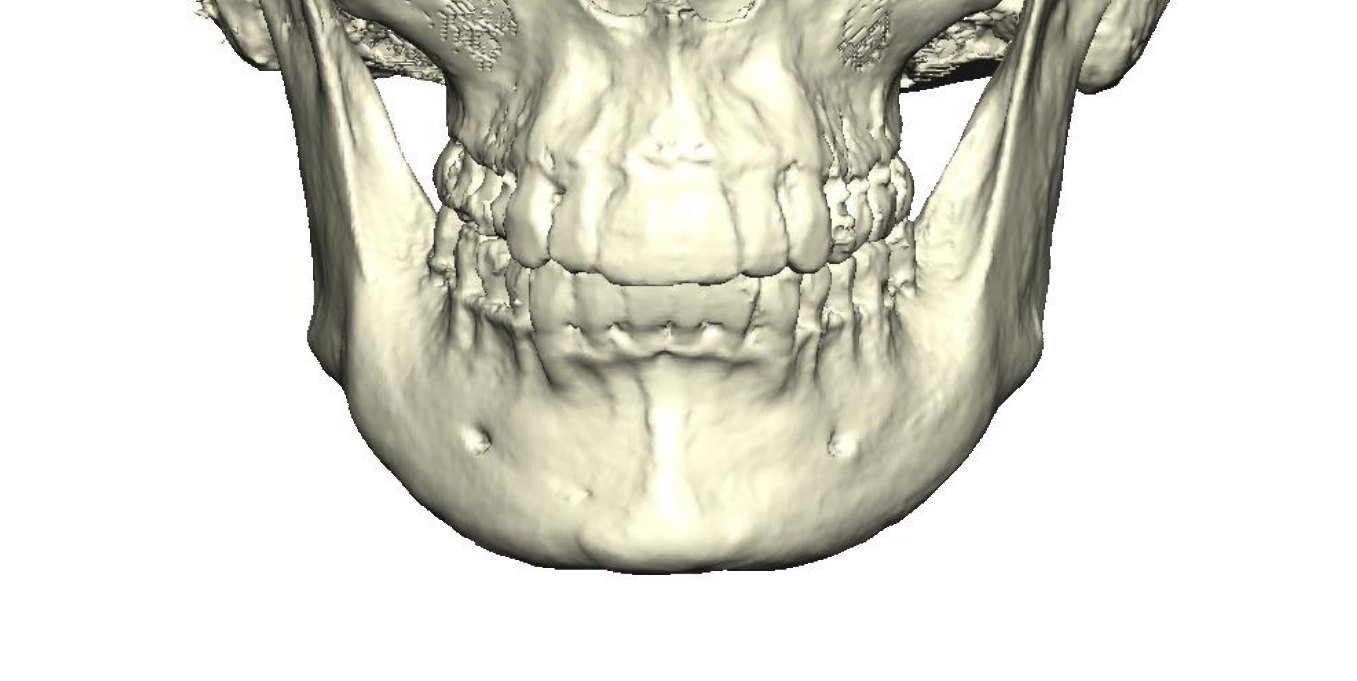
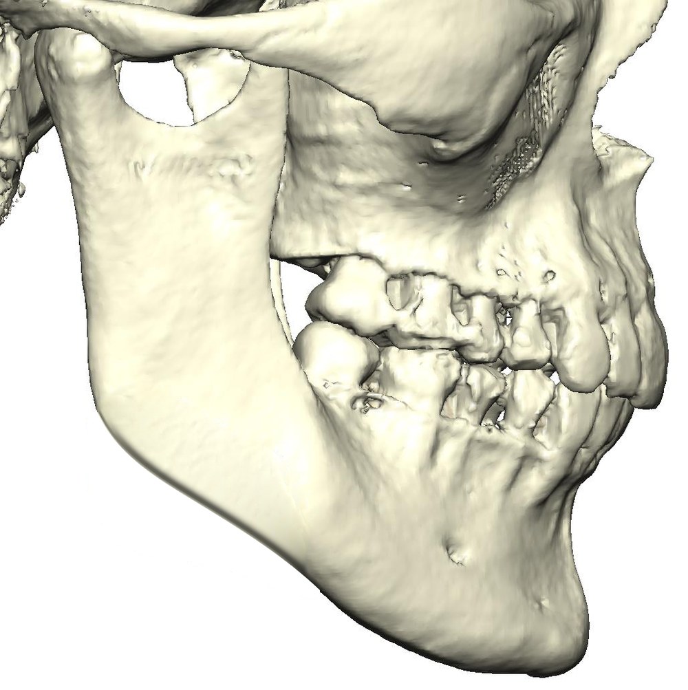 Before
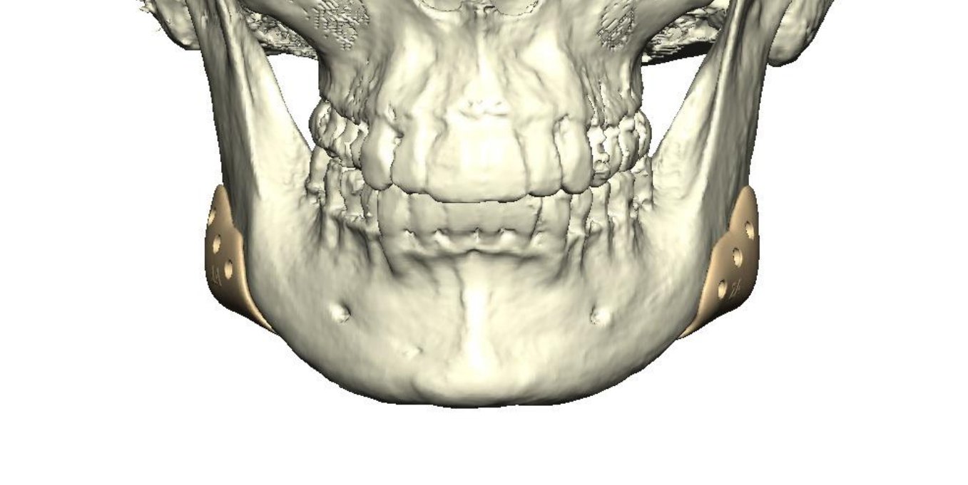
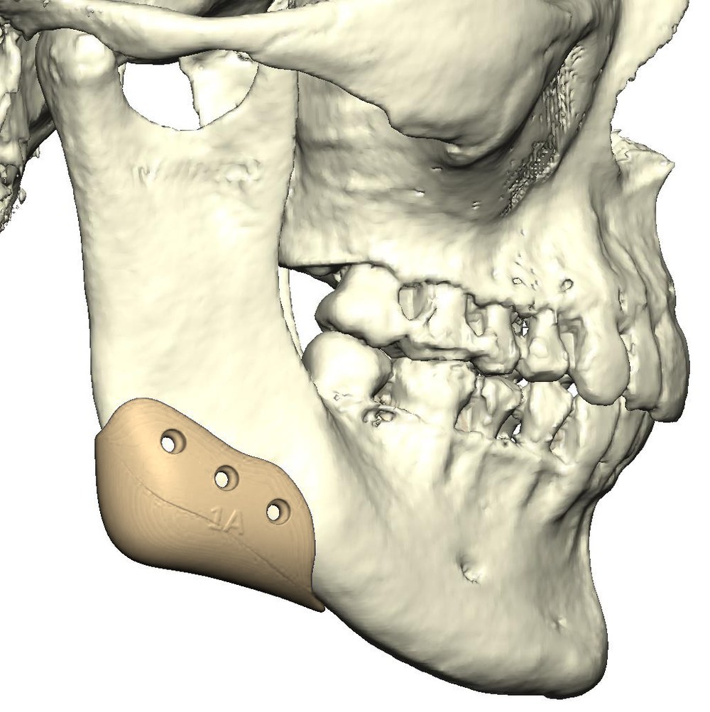 Planned
Before and planned
Each pair shows the 3D model before and with the planned implants, at the same angle and scale. The implants sit on the outer surface of each jaw angle and extend it downward and outward, adding vertical length and a more defined angle (planned).
Right and left sides, same angle and scale in each row. The dashed gold line marks the original jaw outline; the implant adds length below and behind it at the jaw angle.
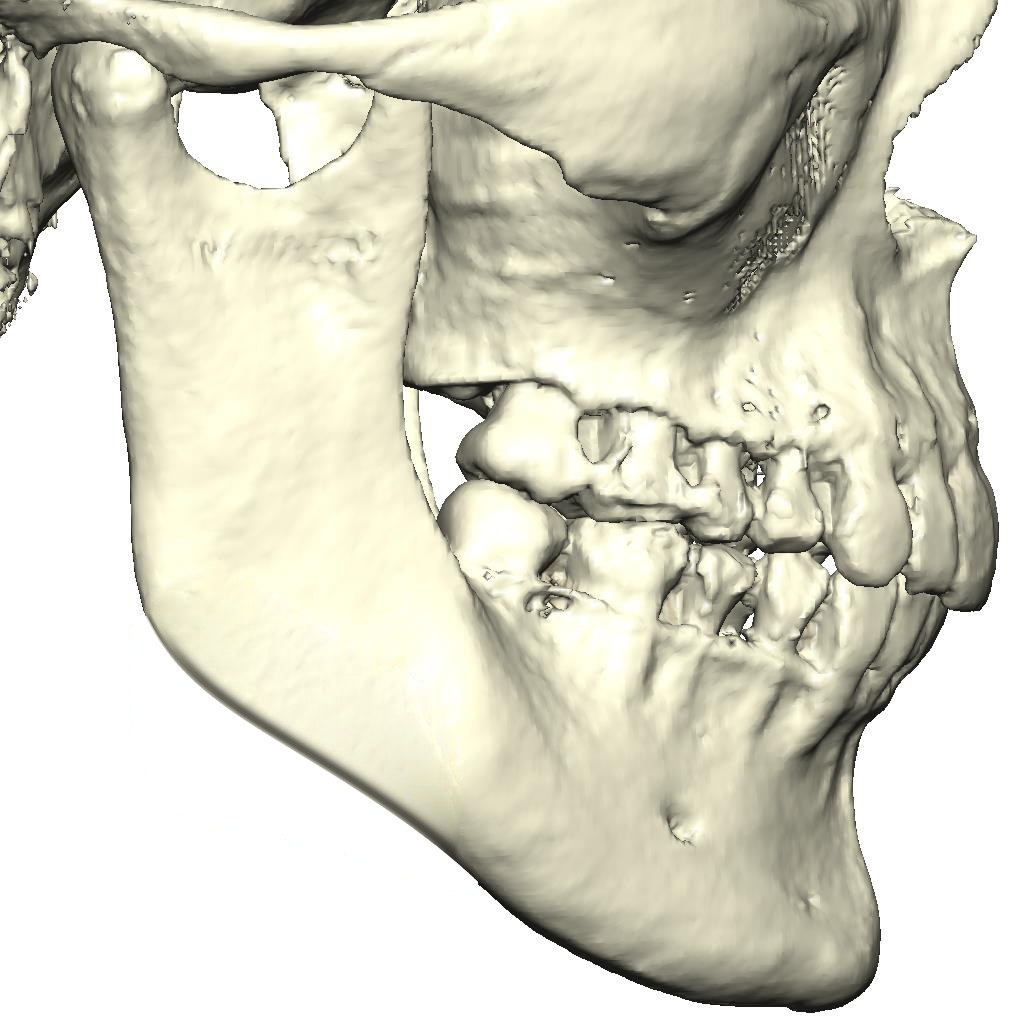
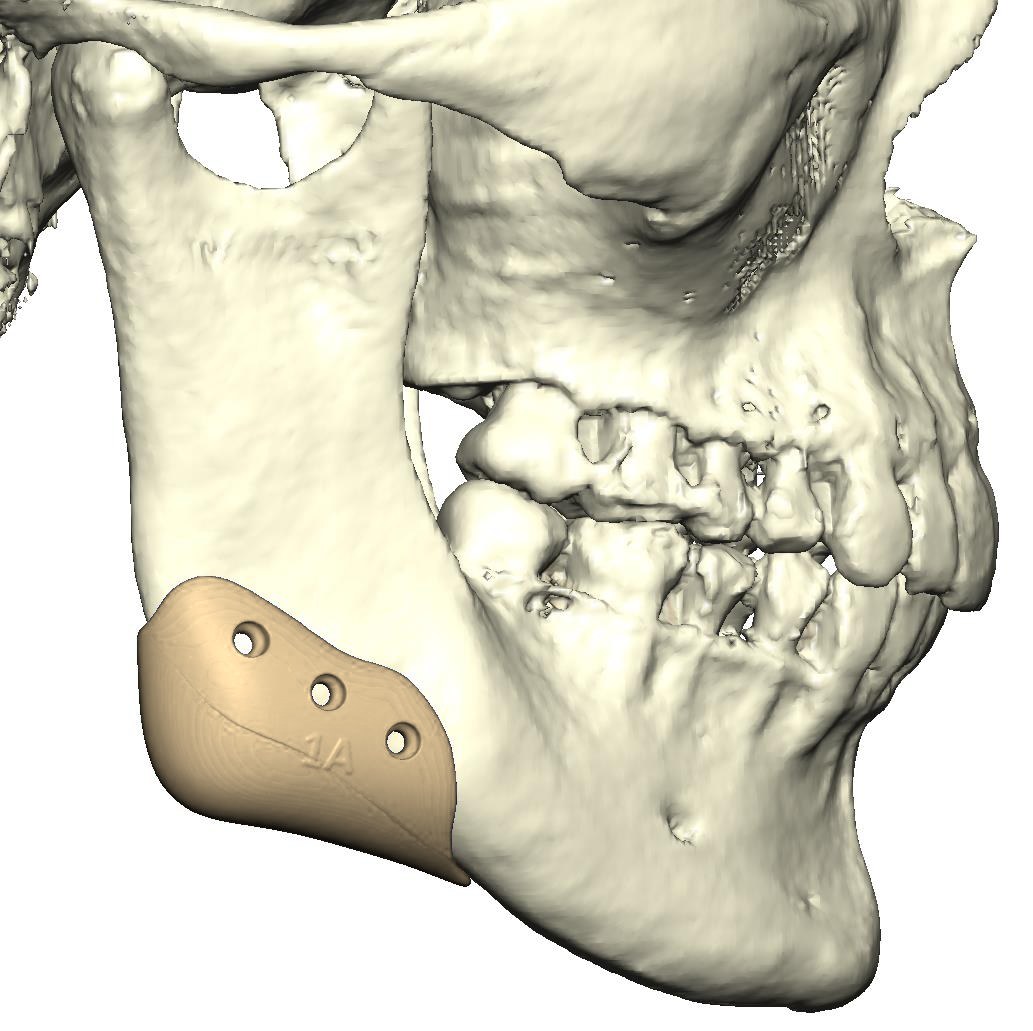
Diagnosis & concern
Short ramus height and a steep mandibular plane angle; goal: added vertical length and definition at the jaw angles.
Short ramus and a high mandibular plane angle, with little definition at the jaw angles.
Implant design & fit
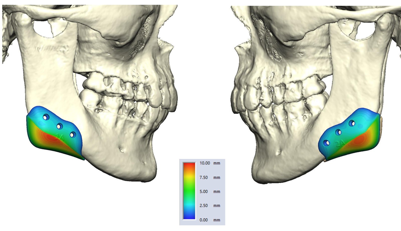
The implants are designed on the 3D model to fit the bone at each angle. The thickness map shows each implant thickest over the angle and thinning toward its edges, on a scale of 0 to 10 mm, so it blends into the jawline. Fixation is planned with 2.0/2.3 mm screws.
| Segment | Planned movement | Amount (from plan) |
|---|---|---|
| Width between the angles | From below | 88.3 → 93.4 mm |
| Implant 1 | Right mandibular angle | PEEK, 2.0/2.3 mm screws |
| Implant 2 | Left mandibular angle | PEEK, 2.0/2.3 mm screws |
| Thickness | Colour map scale | 0 to 10 mm |
| Vertical length | Jaw angles | Added (planned) |
Planning steps
- CT scan converted into a 3D model of the skull and mandible
- Right and left implants designed to add length and definition at the jaw angles
- Implant thickness mapped to set the planned contour
- Screw positions and lengths planned on the model
Where
Planned at Maxillo-Facial Surgery Institute, Irvine. Our Surgeons